 English
 ClearTrack is the latest addition to AB Dynamics’ Automated Driverless Testing solution. It is a LiDAR-based object detection system designed to enhance driverless vehicle testing by identifying and avoiding unexpected obstacles on the proving ground. We sat down with ClearTrack project leader and Senior Embedded and Control Software Engineer at AB Dynamics, Jonathan Barry, to learn more about how the system works, what problems it solves, and why it matters to automotive test teams.
Q: Let’s start from the top, what exactly is ClearTrack?
JB: ClearTrack is an object detection system that can be fitted to AB Dynamics driverless test vehicles to enhance their safety case. In simple terms, its job is to identify potentially hazardous obstacles, such as wildlife, debris or cars, that might appear on the track during driverless testing. If something is detected, and judged to be a collision risk, the system will automatically trigger the vehicle to stop.
Q: Why is this an important addition to the driverless solution?
JB: Driverless testing is becoming increasingly common in the industry. Removing the human driver from long, repetitive or potentially harmful tests eliminates fatigue-related variability and reduces risk. It also enables teams to run multiple vehicles simultaneously from one base station to significantly increase efficiency.
Our customers are experiencing these benefits and are now looking to rapidly scale its use. Running a large fleet would significantly increase the operator's workload and it would be difficult to manage them all safely. And that’s where object detection comes in. It detects and classifies obstacles in real-time and intervenes if there’s a genuine collision risk. This makes it much easier to monitor the test fleet and adds an extra layer of safety to the operation. Ultimately, it allows test teams to deploy driverless systems more confidently and at greater scale, whilst also protecting expensive prototype vehicles and reducing downtime.
Q: How does ClearTrack work?
JB: The system uses a solid-state, ultra-long-range LiDAR sensor mounted on the vehicle roof. This provides tens of thousands of reflected data points every second. ClearTrack filters and processes that data to determine the shape, position, and direction of any obstacle in the vehicle's path.
What’s unique is how it integrates with our robot control system. Because we command the future path the vehicle will follow, we can make more informed decisions about whether an object is actually in the way. This reduces unnecessary stops to keep test programmes on time.
Q: Are there any other ways it minimises false positives?
JB: ClearTrack can be finely tuned to filter out obstacles that don’t pose a genuine risk of damage to the vehicle, such as low lying or sparse foliage. This can be done using ClearTrack’s configurable settings, which also allow the user to control the sensitivity of the system. The object height filters are particularly useful if you need to pass through tunnels or under bridges on your track. This all helps keep testing efficient without compromising safety.
Q: What risks do driverless test vehicles face on proving grounds and how does ClearTrack mitigate them?
JB: Even in well-managed proving grounds, things like fallen branches or wildlife can unexpectedly end up on the track. For example, we’ve had cases of wild deer or even turkeys wandering into test areas.
When you are dealing with rare and expensive prototype vehicles, the last thing you want is to bump into a local deer. Even a relatively small collision can have a big impact in terms of time lost. You could try to solve this with fencing or walls, but that gets extremely costly, especially if you’ve got large facilities that need to be managed and maintained; they are also extremely good at keeping animals trapped inside the fenced area!
Q: What were the toughest technical challenges in developing it?
JB: One of the key challenges has been ensuring the system can reliably filter out features of the test track, such as harsh durability surfaces, to avoid false positive detections, whilst also still being sensitive enough to detect small hazardous obstacles. To overcome this, we’ve drawn on our extensive experience of automating driverless testing and supplemented this with real-world testing on the type of proving grounds our customers use.
Q: What kinds of vehicles and test cycles can ClearTrack be used with?
JB: Pretty much anything. The system uses commercially available roof-bar mounts, so installation is quick and simple. It’s designed to work at speeds up to 130 km/h, which meets key requirements for OEM testing, and it’s built to cope with high-vibration conditions too. So, whether you are carrying out long mileage accumulation tests or tough durability tests, ClearTrack is capable of handling it.
Q: What’s next for ClearTrack?
JB: We’re always looking at ways to improve system performance and make it even more adaptable. Right now, the focus is on deploying it to customers and collecting feedback from real-world use. We have integrated a new feature that saves the last two minutes of data if there is an issue. This is sent back to us at AB Dynamics and used to debug and improve the system. That feedback loop is key to making sure the system continues to evolve in line with how test facilities are operating in practice.
Key takeaways:
- ClearTrack is an integrated object detection system that identifies and avoids hazardous obstacles during driverless vehicle testing, enhancing safety and reducing risk.
- It uses a long-range solid-state LiDAR sensor and seamlessly connects to AB Dynamics’ robot control systems for real-time decision-making.
- Designed for fast deployment, ClearTrack mounts to almost any vehicle using standard roof bars and supports testing at speeds up to 130 km/h.
- It helps avoid expensive damage and downtime by detecting genuine obstacles while ignoring minor, non-threatening debris.
- The system enables more efficient test operations, allowing operators to safely manage more vehicles across wider test areas with reduced workload.
For more information on ClearTrack, click here or watch our latest video.
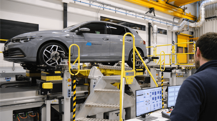
AB Dynamics specialises in the design and manufacture of K&C (kinematics and compliance) test machines for the automotive industry. In this blog post Matt Dustan AB Dynamics Director, Laboratory Test Systems, does a deep dive into this technology. He explains exactly why K&C test machines were developed and what they are used for, how virtual testing integrates with them, and what the future of K&C testing holds.
How does K&C testing work?
Before the existence of K&C test machines, there was no standardised method for comprehensively generating the kinematics and compliance characteristics of a vehicle’s suspension system. Instead, to develop physical design adjustments, dynamics engineers had to rely heavily on matching subjective track evaluations with their own experience. K&C machines changed the game by making standardised, objective assessment possible and practical. In essence, a K&C test machine applies very accurate movements and forces into a vehicle’s suspension system. The resulting data provides engineers with a thorough understanding of a vehicle’s ride and handling characteristics.
In most instances, a K&C machine will clamp onto the vehicle’s body and manipulate the vehicle’s wheels to provide the necessary inputs. This enables a combination of roll, pitch, bounce and yaw motion to be applied to the vehicle body to simulate cornering, braking and traction.
However, at AB Dynamics, we do things a little differently. Our K&C test machine, the SPMM, is unique in that instead of moving the vehicle’s wheels to apply the required inputs, it moves the vehicle body, and the wheels remain relatively static. This moving centre table design means the ground plane, which in this case is the road, remains fixed. This more faithfully replicates what happens in the real world because roads don’t move! We can confidently say that this approach results in more accurate data.
What types of K&C tests are there?
There are hundreds of tests that can be conducted on our K&C machine. Some of the industry standard tests include bounce and bounce-pitch, roll, steering, cornering, braking, traction, and lateral and longitudinal compliance. But we also work closely with our customers to create bespoke tests too. For example, horizontal simulation tests that aim to determine the individual contributions of kinematics and compliance effects during lateral and longitudinal manoeuvres, such as cornering and braking.
What are kinematics and compliance test machines used for?
There are lots of use cases for a K&C test machine, it really is a multi-faceted tool. One of the most common use cases is to benchmark competitor vehicles to thoroughly understand the handling characteristics and determine trends in the market. It can be used throughout the vehicle development process to assess suspension systems. It is also used to monitor the performance of early production vehicles to ensure they remain within the prescribed tolerances.
One of our first K&C machines, was installed at Horiba MIRA in 1995 and has tested in excess of 3,000 vehicles, helping to develop next-generation vehicles. Another, being used by a Chinese vehicle manufacturer, is processing more than 150 vehicles every year, including benchmarking and vehicle development activities.
What about virtual K&C testing using simulation?
To do this a multibody simulation (MBS), also referred to as multibody dynamics (MBD), is required. It is a computer-aided engineering (CAE) method used to simulate and analyse the behaviour of mechanical systems. In vehicle dynamics and K&C testing, it replicates a suspension system by modelling interconnected rigid or flexible components linked through joints and actuators. These components interact and move based on applied forces, just as they would during real-world K&C testing, but in a virtual environment.
How does physical K&C testing integrate with MBS?
K&C testing is essential for MBS as it provides real-world data on how a specific vehicle’s suspension performs under various forces. The K&C data allows the MBS model to be correlated to real-world scenarios, ensuring the virtual simulations are highly accurate.
MBS software, such as RACE (Rapid Axle Concept Evolution), offers a cloud-based solution where physical K&C data can be integrated seamlessly. The tests performed virtually in RACE correspond directly to those conducted on AB Dynamics K&C machines, ensuring a precise match between physical and simulated results. This allows engineers to replicate real-world conditions within the virtual environment, fine-tune suspension parameters, and analyse vehicle performance across a range of scenarios.
What is the future of K&C testing and how is it changing?
We are seeing more manufacturers adopting virtual test and validation processes to help accelerate the development of new vehicles. As a result, simulation and digital vehicle models are now critical tools in the development process but correlation with the real world is critical to success. K&C test machines are now being used to generate all the chassis-based data required to create high-fidelity vehicle models.
On top of this, vehicles are also being integrated into Hardware-in-the-Loop (HIL) simulation testing using K&C test machines. This enables a physical vehicle or sub-system of a vehicle to be tested with the resulting data being fed in real-time to an external simulation environment. This is particularly useful for the development of active and semi-active chassis control systems.
K&C testing has been a fundamental stage of automotive development for decades now and with the increasing importance of virtual development and the integration of HiL this is unlikely to change anytime soon.
Key takeaways
- K&C test machines apply very accurate movements and forces into the vehicle’s suspension system
- AB Dynamics’ SPMM K&C test machine is unique as it moves the vehicle body whilst the wheels remain relatively static, therefore faithfully simulating on-road vehicle behaviour
- K&C machines allow an MBS model to be correlated to real-world data, ensuring the virtual simulations are highly accurate
- Manufacturers are increasingly adopting virtual test and validation processes to help accelerate the development of new vehicles
- Vehicles are also being integrated into Hardware-in-the-Loop (HIL) simulation testing using K&C test machines
For more information on our K&C test machines, click here.
This year AB Dynamics and its sister company Dynamic Research Inc. (DRI) celebrate the 10th anniversary of the first sale of the Guided Soft Target (GST) surrogate vehicle target system. In this blog, Joseph Kelly, Chief Engineer at DRI, explains how the GST has set the global standard for 3D vehicle targets and has helped to revolutionise the testing and development of lifesaving ADAS technologies.

The GST test system consists of the Soft Car 360, an impactable dummy vehicle target attached to a low-profile robotic platform designed to be run over by vehicles. In this article, we will be looking at the origins of the GST and the industry trends that have shaped its design.
The history of the GST
The GST’s story starts in 2007 when crash avoidance technologies, such as Automatic Emergency Braking (AEB), were still in their infancy and so too were the systems to test them. A variety of targets, ranging from simple radar reflectors to partial vehicle representations (both static and dynamic), were developed to aid in the evaluation of rear end collision avoidance and mitigation systems, but these had limitations restricting approach speeds and angles, as well as lateral offsets. Additionally, some of the dynamic systems required the presence of other vehicles to tow the targets, or suspend them from above, which could sometimes adversely affect the performance of the vehicles under test.
It was at this time that DRI collaborated with NHTSA (National Highway Traffic Safety Administration) on the ACAT (Advanced Crash Avoidance Technologies) project, together with Honda. The project aimed to develop practical methods for evaluating the effectiveness of emerging ADAS technologies. A key phase of the project was to establish the test requirements in order to conduct full-scale testing of the technologies.
The project identified three key vehicle-to-vehicle scenarios that would need to be tested, which were head on, rear end and crossing paths.
These tests necessitated a dynamic solution that was strikeable from multiple angles that:
- Did not damage the vehicle during test,
- Did not present a safety risk to test personnel,
- Was easily reconfigurable and enabled close coordination of vehicles with regard to conflict conditions such as closing speed and angle, and
- Could easily be reset after impact for further testing.
The solution: the GST system. Through this project, DRI became fundamental in finding ways to help the industry test and develop first-generation collision avoidance systems that have since been developed into today’s technologies.
The initial development of what would become recognisable as the GST system used a simple vehicle target constructed from foam, fitted to a first-generation version of the GST platform, which was affectionately known internally as the ‘Turtle’. It was the first self-propelled dummy vehicle target that could be safely run over, providing unrivalled testing flexibility. Designed initially for detection by lidar, the system’s visual representation of a vehicle and its radar reflectivity were less relevant. The entire system was designed and manufactured in-house at DRI, including the platform’s navigation and control system.
DRI recognised that the appearance and durability of the target needed to be improved to be useful to manufacturers using camera and radar systems and this formed the core development path for the following few years. A project with IIHS (Insurance Institute for Highway Safety) in 2011 and feedback from other industry experts identified a demand for stable radar reflectivity, which resulted in the introduction of a new reflective material for the Soft Car 360. Other developments included enclosing the foam skins in vinyl fabric “pillowcases”, which allowed the application of photorealistic graphics and increased durability and realism. The result was a first-generation version of the Soft Car 360 that we know and recognise today.
DRI’s involvement in these industry projects led to the development of equipment that is now in use globally to thoroughly test ADAS technologies. Worldwide adoption of standardised tests that rely on this equipment is helping to provide safety ratings of new vehicles to educate consumers and improve road safety.
In 2012 DRI developed what became the first commercially available GST that incorporated all the various features to make it representative to a variety of sensor systems. Later that year, DRI began its partnership with AB Dynamics to further develop the product and the first unit was delivered to an Asian OEM in 2013.
This partnership allowed customers to experience AB Dynamics’ tried and tested control hardware and software from the steering and pedal robots in a driverless platform. It also allowed for seamless synchronisation between robots thanks to AB Dynamics’ patented Synchro software.
In 2014, DRI developed the second generation GST in collaboration with NHTSA. This project involved reducing the radar reflectivity of the platform and increasing the acceleration and top speed, to cater for the growing variety of tests being carried out. There was also a heavy-duty version developed for trucks. In 2018, AB Dynamics introduced the MK2 GST platform, bringing improvements to the market, such as a lower overall profile, 100 km/h top speed and improved path following.
The collaboration between AB Dynamics and DRI proved to be a great success resulting in the GST’s approval for use by Euro NCAP and NHTSA as its Global Vehicle Target in 2018. The relationship further strengthened when DRI joined the AB Dynamics group through an acquisition in 2019.
In 2020, during the COVID-19 pandemic, AB Dynamics introduced the GST 120, the highest top speed GVT on the market. This was an incredible engineering achievement as although a 20 km/h increase in speed doesn’t seem much, an astounding 70% increase in power is required. Alongside its increased top speed, an Anti-lock Braking System (ABS) was also introduced, which later became standard on all GST products.
Since its initial introduction the GST has been continually developed, particularly to improve its realism in line with the increasing sophistication of ADAS perception and classification technologies, and the Soft Car 360 is currently in its seventh revision.
Industry drivers and challenges
When the GST was first introduced ten years ago, advanced crash avoidance technologies were usually found on higher-end luxury vehicles. Thanks, in part, to the ACAT projects these technologies were becoming more mainstream and Volvo was the first OEM to fit AEB as standard on all new models in 2014. The continued development of these technologies and an increased focus on safety regulations has driven the mass adoption of collision avoidance and mitigation systems.
One of the most used sensor systems is radar. It scans the world very efficiently but often lacks definition and is limited in providing data on verticality, which would be useful in correctly classifying objects. Increasing the resolution of radar systems is a key area for development for OEMs. The GST system has been future-proofed in this respect as the GST platform has been designed to minimise radar reflectivity, whilst the Soft Car 360 has been optimised from top to bottom to reflect radar realistically.
Although very efficient in the way it transmits and receives data, radar does have its limitations. As a result, OEMs are now moving towards sensor fusion, combining a variety of sensors to more accurately perceive the world ahead. For example, a camera and radar system sense the world in disparate but complementary ways leading to a much better perception system than would be possible from a single type of sensor.
As these technologies have matured and adoption has increased, the challenge for the industry has shifted from simply avoiding and mitigating a potential crash to them being more usable on the road and not issuing false positives. This is critical in translating these technologies into real world road safety improvements.
To achieve this the vehicle must correctly discern what it can and can’t ‘drive into’. A good example of this problem are steel trench plates, used for covering up holes or trenches in the road during road works. They are large and reflective to a radar system, just like a car, so they could be mistakenly perceived as a parked car, as a result, vehicles could apply full braking as they approach. This is where a combination of sensor systems should be able to correctly identify the object and make the correct decision to not intervene.
The future of the GST
These industry trends have driven the development path of the GST system. The Soft Car 360 has been developed in collaboration with industry partners, including sensor manufacturers and OEMs, through workshops coordinated by Euro NCAP, NHTSA, and IIHS. This collaboration has been critical in improving the realism of the target and understanding how it is perceived by the many different sensor technologies used on a vehicle.
Additionally, the quantity and complexity of ADAS testing is expected to continue to grow exponentially and so too are the tools used to test these systems. The hatchback version of the GST has been approved for use in NCAP tests since 2018 but there is a range of vehicle targets available, including a micro, sedan and estate version. This range will continue to expand to provide customers with the variety required to thoroughly test a vehicle’s sensor system.
One of the next big steps in active collision avoidance technologies is likely to come from increased connectivity. The ability for a vehicle to communicate with infrastructure and other vehicles around it increases awareness of potential dangers and the time to react. The integration of connectivity, or V2X (Vehicle-to-Everything), will significantly impact the testing landscape. AB Dynamics is participating in the SECUR project (Safety Enhancement through Connected Users on the Road), which aims to create a coherent proposal for V2X testing and assessment protocols for Euro NCAP. AB Dynamics’ key input into the project is to help define a specification for connected targets to support V2X testing in the future.
The GST timeline:
- 2007 – DRI starts collaboration with Honda and NHTSA on the Advanced Crash Avoidance Technologies (ACAT) project.
- 2008 – DRI develops the Low-Profile Robotic Vehicle (LPRV) ‘Turtle’, an early version of what would become the GST platform, and a simple Soft Car 360.
- 2010 – DRI continues development of the Soft Car 360, integrating a multi-panel construction design.
- 2012 – DRI signs collaborative agreement with AB Dynamics.
- 2013 – First GST delivered to customer.
- 2014-2015 – The second generation GST is developed for NHTSA, including heavy duty truck compatibility.
- 2018 – The GST is approved as the official Global Vehicle Target (GVT) by NHTSA, IIHS and Euro NCAP. The GST MK2 platform introduced with various improvements, higher top speed (100 km/h) and lower overall height.
- 2019 – DRI acquired by AB Dynamics.
- 2020 – AB Dynamics becomes a partner in the SECUR project featuring the GST system. The GST 120 introduced, the fastest GVT in the market, with a top speed limited to 120 km/h. Also introducing improved path following at high speeds as well as ABS to the GST line up.
- 2022 – GST 120 and Soft Car 360 were officially approved by Euro NCAP under Technical Bulletin 29.
- 2023 – It is the ten-year anniversary of the delivery of the first GST. GST and V2X demonstration for the SECUR project.
For more information on the GST test system or to arrange a demo, contact us at info@abdynamics.com
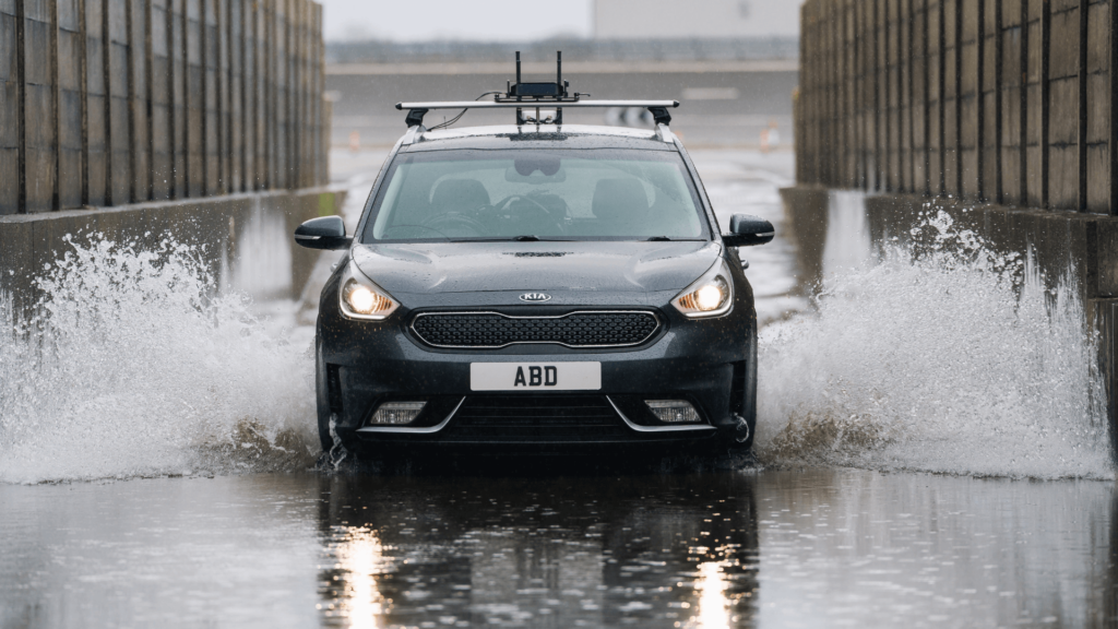
Automotive test systems supplier AB Dynamics claims the recent growth in wireless data transfer from the increasing use of driverless traffic in automotive testing is causing significant issues for the industry.
Increasingly complex test scenarios require the use of driverless vehicles and other moving elements, such as ADAS targets, which must all be in constant communication with each other. This increase in data transfer can result in interference and signal dropout, triggering fail-safe architectures to stop the test, meaning that test scenarios have to be reset and repeated.
Because ‘swarm testing’ – where five or more vehicles are being tested at any one time – is now commonplace, the chances of interference increase. And, with more devices using wi-fi, the number of costly stoppages during testing is likely to continue on an upward curve without using more robust telemetry solutions.
The company feels that these challenges are set to become more acute with the proliferation of autonomous vehicles and the expansion of ADAS testing. For example, since 2014, the number of ADAS test scenarios included in the Euro NCAP assessment has increased by 650%.
Jeremy Ash, sales director at AB Dynamics, explained, “In 2007 we supplied our first driverless test system to Groupe Renault, which enabled them to conduct durability or dangerous tests with a single vehicle without the need for a driver.
“Today, the majority of our customers have a significant number of driving robots, GSTs (guided soft targets) and LaunchPads, to carry out the required testing for modern vehicles. All of these are continuously transmitting data during a test. This level of activity creates interference and disrupted communication between vehicles and base. When this occurs, even for just one second, we stop the test for safety reasons.”
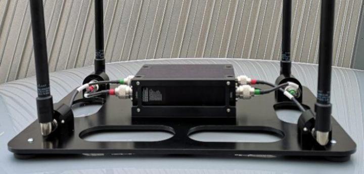
To combat this problem, the company has developed TrackFi PowerMesh, a communications system specifically designed for automotive testing. It claims the dual-band IP radio offers dependable data transfer from vehicle-to-vehicle and vehicle-to-base through secure mesh networks, which is more reliable than standard WLAN technology.
Renault is already using the system for its testing programs, as Grégory Lesueur, ADAS equipment coordinator at Groupe Renault, highlighted, “TrackFi PowerMesh has delivered us considerable benefits. We have found it very efficient to use and have experienced enhanced communication between vehicles and ADAS targets. It enables us to achieve so much more in our track testing program because downtime is significantly reduced.”
The system operates across two frequency bands, dynamically switching between 2.4Ghz and 5Ghz RF transceivers, ensuring optimum connectivity between multiple vehicles in a test scenario and secure transfer of high throughput data. It is suitable for use on vehicles in conjunction with AB Dynamics’ ADAS platforms or as static nodes to mount trackside.
“We have designed the latest generation radio to provide a high level of modularity, ensuring that it is suitable for as wide a range of test scenarios as possible,” added Ash. “For example, the four omni-directional antennas are foldable, making it ideal for ADAS testing where collision with a guided soft target could otherwise cause damage. Static nodes can also be hardwired to a power supply for permanent use or used with portable battery packs for up to 24 hours between charges for flexibility of testing. The entire system can be easily set up or transferred between vehicles, targets or locations."
All of our steering robots have an angular encoder built in; a feedback device that reports back to the control system what angle the steering robot is at.
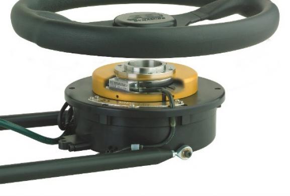
Every control loop needs a feedback signal – a measure of “where I am now” which it can compare with “where I should be now” to generate corrective action. When a steering robot is controlled in angle mode, the feedback device is the angular encoder. We use a range of encoders in our driving robots to suit the particular requirements of each actuator.
These include optical encoders, such as the Renishaw system in the SR30 steering robot shown above, magnetic devices and inductive encoders.
The definition of a steering input as required by a test standard will include an angular input (e.g. turn the steering 90 degrees to the left) and – normally – a tolerance, which might be +/-1 degree. The tolerance defines whether an input of 90.5 degrees is acceptable or not if the target is 90 degrees.
Historically, tolerances would have been defined based upon what an expert human driver could achieve. Today, a robot can achieve accuracies far beyond what any human driver could do, and consequently, test tolerances are being tightened.
That being said, there is no test in the world which requires steering angle measurement at the accuracy with which AB Dynamics steering robots can measure. Our entry-level model, the SR15, can measure steering angle at a resolution of 0.006˚, that’s 1/60,000th of a revolution. The rest of the range measures steering angle even more precisely (the SR60 can measure 1/600,000th of a revolution!). So why do we use such high-precision encoders? The answer is found in control theory. Our robots are famous for being able to achieve incredible control fidelity; able to turn at high speeds and stop with zero overshoot.
Achieving smooth motion control at a range of speeds is the reason why we need such accurate position feedback. Our motion control operates at a frequency of 4kHz, so we need to know 4,000 times per second where the robot is. The more accurately we know, the more smoothly we can adjust its motion.
And that’s why we measure the steering angle so precisely!
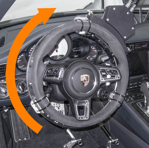
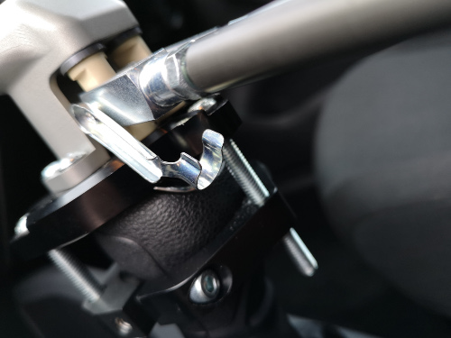
In this blog post, we look back at how we designed the gearshift robot. At the time, there were one or two other devices on the market which were used in chassis dyno testing, where the vehicle is stationary in a test lab. These used heavy and complex mechanisms to move the gearstick through its range of motion, and didn’t allow you to sit in the driver’s seat.
Our driving robots are designed primarily for use on a test track, and they are all designed to allow a human driver to sit in the vehicle. Even if you plan to perform your tests with no-one onboard, it’s always an advantage to be able to jump in the car and drive normally between tests.
We set out to design an actuator that was simple, lightweight and could be installed in almost any vehicle. And just like our other robots, it had to accommodate a human driver.
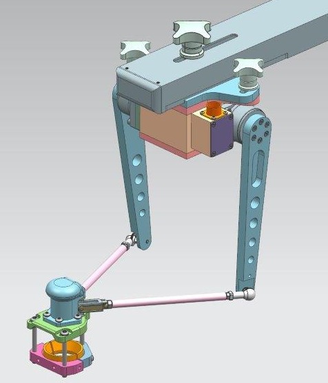
After looking at a number of arrangements, we settled on our basic design. By using a pair of actuators, each with a rotary lever which is linked to the gearknob, we can achieve a full range of x-y motion.
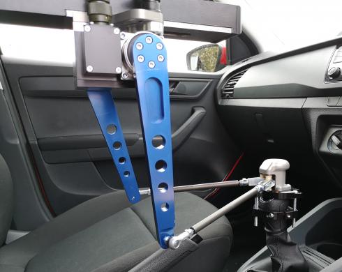
One challenge was to be able to mount the actuator in the vehicle. Another common thread across our driving robot range is the ability to mount in almost any vehicle without the need for custom bracketry or drilling holes. We chose to use our ultra-rigid transducer strut as the basis for installing the gear robot.
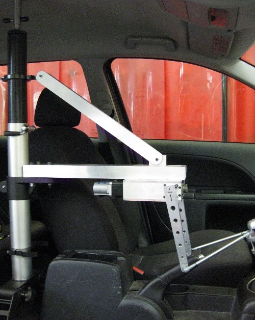
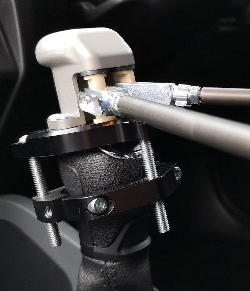
From the prototype above, we made various refinements to arrive at our finished design.
The links feature quick-release couplings, so that you can unhitch the robot from the gearknob.
We added a gear knob on top of the clamp which attaches to the vehicle’s gearstick, to make it easier for the driver to change gear.
The gearshift robot was one of the stars of the show when our robots featured on a Guy Martin tv special. We used robots to convert a standard Ford Transit van into a driverless car, and Guy was blown away by how fast the gearshift robot could change gear.
Path following, a technology first developed by AB Dynamics in 2001, is now well known and in use globally for tests such as the ISO lane change and a raft of ADAS standards. What may be less widely understood is how it can help with many other tests which are not defined in terms of a trajectory to follow. Here we will look at the path following lead-in and how it can help with testing in constrained spaces.
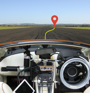
Most objective vehicle dynamics testing is performed on a track called a VDA, which stands for Vehicle Dynamics Area. If the VDA is only just large enough to fit a test in, it can be critical to start the test at the right point on the track, and at the required heading angle. This can be difficult for human drivers, especially at speed.
The RC software includes a number of options for starting a test. As well as manually triggering using the start button, a test can be initiated based upon a wide range of external triggers such as vehicle speed or GPS time. Path following lead-in is effectively a further option, where the steering robot automatically guides the vehicle to the desired location before automatically starting the test itself. This ensures positioning and heading accuracy far in excess of what a human could achieve.
An example where this was used is a sine-sweep test performed on VDA A at IDIADA in Spain. This comprises of a sinusoidal (sine wave) steering input whose frequency and amplitude vary through the test to assess a vehicle’s lateral response at different frequencies.
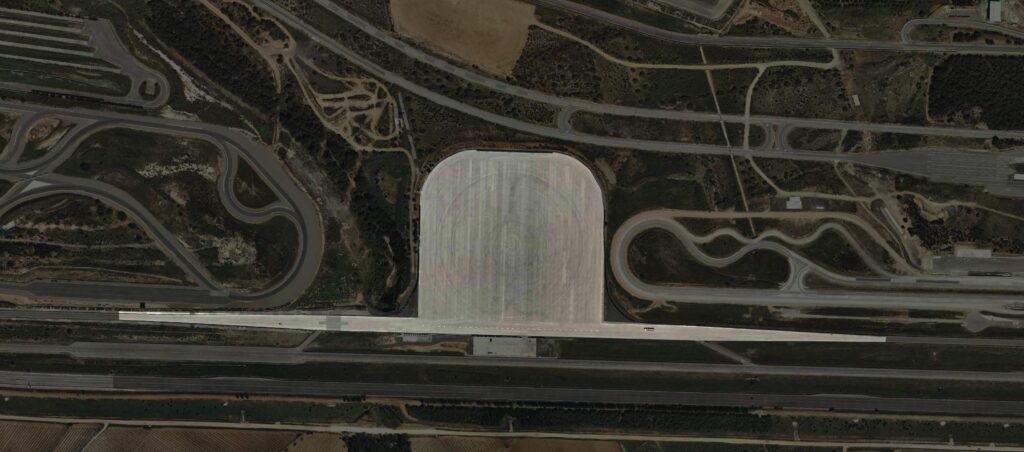
The track used at IDIADA, Spain. The test duration meant that both the entry and exit roads from the VDA were required.
If a test driver was doing this test by hand, they would make small adjustments to the sinusoid to keep the vehicle on the track. This is a skilled driving input which takes a lot of practice, but the resultant data would not be as good as the perfect sinusoidal input that the robot can generate. Using a robot guarantees a perfect blended sinusoid but fitting the manoeuvre onto the test track can be a challenge. Hence, using a path-following lead-in gives you the best of both worlds – perfect data even when testing in confined spaces.
Once the appropriate starting position had been found allowing the test to be run in full within the available space, a path was created which led up to this spot. The driver simply positioned the vehicle further down the track and allowed the robot to guide the vehicle onto the path and up to the starting position, whereupon path following ceased and the sinusoidal playout was triggered automatically. This could be repeated as many times as necessary without requiring any further skilled input from the test driver.
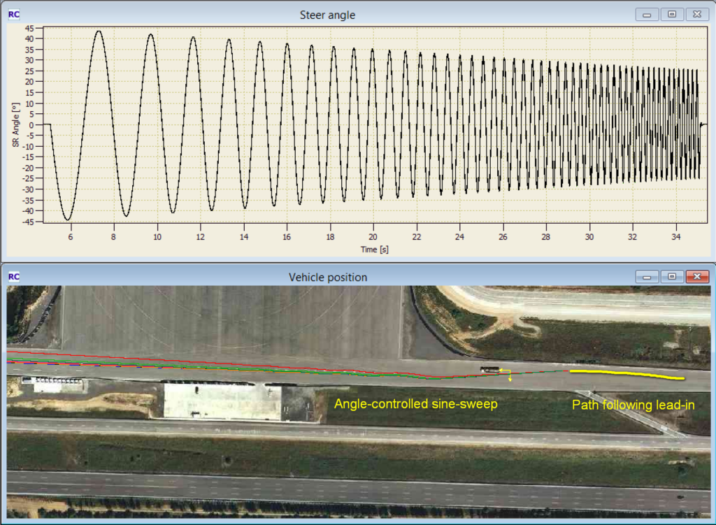
7 runs of data. The top graph shows the angle-controlled part of the test, demonstrating the perfect control and repeatability. The lower picture shows the test track and the motion of the vehicle, as well as showing the path following lead-in used.
A steering robot with path-following was used for this testing, as well as an accelerator robot to maintain the correct speed. The path following lead-in function is part of the PF Vehicle Dynamics software module.
Read more about how path following and is used in ADAS testing, vehicle dynamics and durability testing.